Product No. 14104
This sophisticated 15-output electronic power distribution module replaces conventional relays, fuses, and circuit breakers for managing power to lights, motors, ECUs, data loggers, and more—simplifying wiring and boosting reliability.
Key Features & Capabilities
Each output (8 × 20 A and 7 × 8 A) offers programmable over-current, short-circuit, and thermal protection, helping to safeguard vehicle systems.
Outputs can be programmed in 1 A steps and controlled using switch inputs, CAN messages, or custom logic, with support for up to 200 logic operations (e.g., Flash, Pulse, Toggle, AND/OR).
16 switch inputs supporting voltages between 0–51 V (resolution 0.2 V), ideal for triggers and monitoring.
Continuous diagnostic feedback (input/output voltage, current, error status, temperature) is available via CAN messages.
Specifications at a Glance
Outputs: 8 × 20 A (20 A cont., 115 A peak); 7 × 8 A (8 A cont., 60 A peak)
Switch Inputs: 16, 0–51 V range, 0.2 V resolution
Communications: CAN bus for configuration, control, and diagnostics
Connectivity: 1 × 34-pin waterproof, 1 × 26-pin waterproof, 1 × M6 stud
Dimensions: & Weight ~108 × 128 × 39 mm, magnesium housing, ~260 g
Protection: Reverse battery and load-dump protection for module and peripherals
Software & Configuration
The PDM is configured using PDM Manager software via CAN (UTC adapter required). It allows complete setup of inputs, outputs, logic rules, firmware updates, and real-time diagnostics.
Installation Notes
Mount the module in a ventilated area—internal temperatures can reach 110 °C. Temperature monitoring and cooling strategies (airflow, heat sinking) are advised.
Ensure proper wiring of the CAN bus with necessary termination resistors and follow MoTeC guidelines for battery feed and grounding.

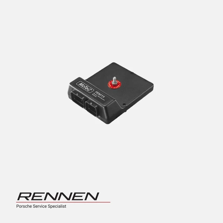 Image 1 of 3
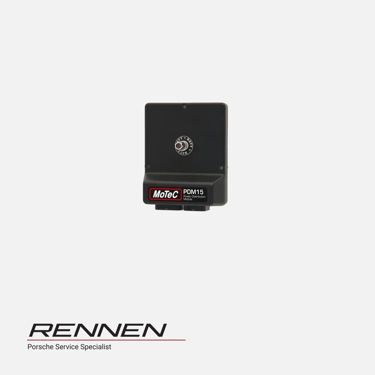 Image 2 of 3
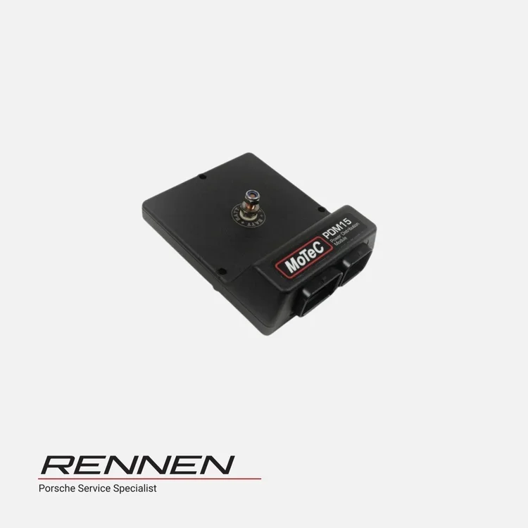 Image 3 of 3